Menu: File -> Batch
Ribbon: tab File > Batch > Batch
Keyboard: Ctrl+B
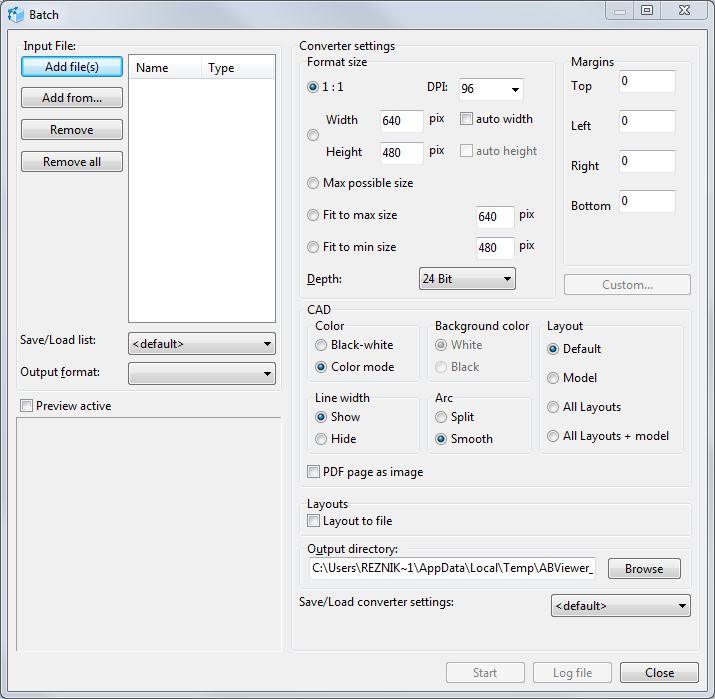
It is used to convert file groups to the BMP, WMF, EMF, JPG, GIF, TIFF, AutoCAD 2000 DXF, AutoCAD 2004 DXF, DWG, PDF, PLT, CGM, SVG file formats with specified settings. Activation of this command opens the "Batch" dialogue box in which export settings are specified. Depending on the selected export file format the corresponding group of settings is activated.
Input file
The list of files for conversion is generated in the "Input file" section. To add and delete files the commands situated to the left from the list field are used.
Add file(s) |
adds one or several selected files to the list. The standard "Open" dialogue box opens in which files are selected. Shift and Alt keys are used to select several files. |
Add from... |
adds all files from the specified directory in "Browse folders" window. |
Remove |
removes one or several selected files from the conversion list. Shift and Alt keys are used for multiple selection of files. |
Remove all |
empties the current file list. |
Save/load list:
The option enables the user to save the current list of converted files or to load files saved beforehand. There are three commands available in the drop-down menu:
▪<default>. Clears the file list field.
▪Save settings. Saves the current file list under the specified name which is entered into "Enter name" window. The name should be unique otherwise confirmation concerning change of the previously saved list will appear. The name of the newly saved file list is added at the end of "Save settings" drop-down list
▪Delete entry. Deletes the file list saved previously. It is necessary to select the deleted list beforehand.
Output format
The option presents the list of formats in which conversion may be carried out. Depending on the selected format in "Converter settings" section the corresponding group of settings is activated.
Output format |
Specified options |
BMP, JPEG, GIF, TIFF |
all the converter settings are available. |
WMF, EMF |
it is impossible to indicate the margin size of the final image, the DPI value and color depth. |
DXF, DWG, PLT |
only CAD section options are available for change. The converted layouts are determined on default "All layouts + model". |
CGM, SVG |
only CAD section parametres are available for change. As the output files of this formats can't be multipage the model conversion is performed on default. |
the output settings become inactive, while exporting into PDF all the settings are made in the PDF Export Options dialogue box, which opens after clicking [Custom...] |
Summary table of file formats conversion:
Input format |
Output format |
||||||
BMP, JPG, GIF, TIFF |
WMF, EMF |
DXF, DWG |
PLT |
CGM |
SVG |
||
Bit-mapped formats: BMP, JPEG, PNG etc. |
✓ |
✓ |
✓ |
- |
- |
- |
- |
WMF, EMF |
✓ |
✓ |
✓ |
- |
- |
- |
- |
DXF, DWG, PLT, SVG, CGM, PDF |
✓ |
✓ |
✓ |
✓ |
✓ |
✓ |
✓ |
Converter settings
This contains settings with the help of which files should be converted. Depending on the selected output format the corresponding group of settings becomes active.
Format size
The option defines size of the output image, color depth and resolution. It is the main parameter in the process of converting into bit-mapped formats.
▪1:1. File conversion takes place at the scale 1:1, i.e. sizes of the input and output files will be the same.
▪DPI. It is used to describe the resolution capacity of the output image. It describes the number of dots per inch. On default this option is equal to "96".
▪Width and height. The option enable to specify the user's sizes of the output image in pixels. On default the sizes are 640х480px The options auto width and auto height set autodetermination of one of the parametres proportionally to another one.
▪Max possible size. The option specifies the maximal possible size of the output file.
▪Fit to max size. The option sets the value for the bigger side of the input file which it will have after conversion. At the same time the smaller part is computed proportionally.
▪Fit to min size. The option sets the value for the smaller side of the input file which it will have after conversion. At the same time the smaller side is computed proportionally.
▪Depth. The option defines the maximal number of colors which can be used in the image setting the number of bits used to save and represent colors while coding one pixel. The bigger color depth is, the bigger the size of the output file will be.
Margins
The option sets the width of the margins around the image of the output file.
Command "Custom"
The option opens PDF Export options in which parametres of the output file are set. The command is active when PDF file format is specified as the output format.
CAD
The option enables to set parametres for input CAD files before their export to the specified format.
▪Color. The option defines the color scheme for the drawing after conversion. Black/white or color mode.
▪Background color.The option sets color of the background for the output file: White or Black.
▪Layout. The list of input CAD file layouts for conversion is set. Command Default produces export of the current layout (model).
▪Line width. The option specifies visibility of line width in the output file.
▪Arc. The option defines the mode of arc display for the output file.
- Split: the arcs will be displayed as a set of short lines.
- Smooth: the arcs will be smoothed.
•PDF page as image. If the option is off, the objects are converted from PDF to DWG and DXF as vector with the possibility of further editing. If the option is off, each layout of the PDF file is converted to DWG and DXF as an OLE-object.
Layouts
•Layout to file. Each layout of a multipage DWG, DXF, PDF file and files of other formats is saved to a separate file of the selected output format.
Output directory
The option defines the place on the disk where storing of conversion results will be produced. Pressing the command [Browse] opens "Browse folders" standard dialogue box to select the output directory.
Save/Load converter settings
The option enables the user to save the current settings of the converter or to load settings saved earlier. The drop-down list contains three commands:
▪<default>. The option returns converter to the original settings.
▪Save settings. The option saves the specified converter settings under the given name. The name is entered in "Enter name" window which appears after selection of this command. The name should be unique. The saved list of settings is added at the end of the drop-down list.
▪Delete entry. The option deletes the converter settings saved previously. To delete them select the list of settings which should be deleted and then select "Delete entry".
▪
Preview pane
Image of the drawing selected in "Input file" list with all defined conversion specifications is loaded to the preview pane. Preview is inactive by default. Ticking of the mode Preview Active switches Preview on.
Conversion report
When conversion is over the dialog box "Batch log file" opens which contains results of all batch conversion launches in the current session the Batch mode. Data of each next launch is saved at the end of the Log file. After closure of the dialog box "Batch" the log file is cleared. It is possible to execute forced clearing of the results of the changes implemented before or to save them to the text document with the help of the commands [Save log file] and [Clear log].
Go to ABViewer