3D Viewer is a display mode of 3D models and surfaces.This mode enables to configure individual visual elements (surface shading, triangulation mesh, edges) display. Lighting and transparency are applied. 3D models can be rotated by moving the mouse with the left mouse button pressed.
Move and rotate 3D models
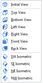
You can move and rotate a model using the mouse. It is possible to customize the view by selecting one of the standard types of 3D model display:
3D Viewer
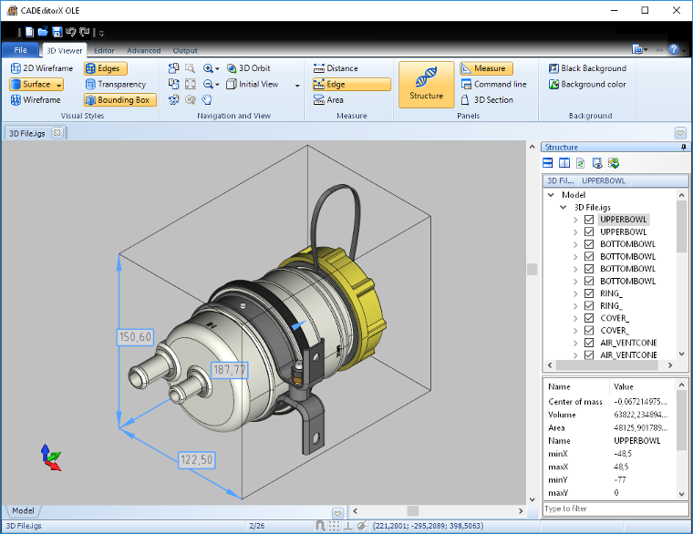
To activate the 3D models viewing mode, click the 3D Viewer button. Different options and modes are available to customize the visual style of teh 3D model display. When the 3D Viewer mode is activated, options and commands in the Visual styles and Tools groups become available:

Visual styles
The 3D Viewer tab includes tools, settings, modes and options for 3D model visual display:
•2D Wireframe
•Surface
•Wireframe
•Edges
•Transparency
•Bounding box
2D Wireframe. Switching to the 2D Wireframe display mode. With this mode only 3D model edge lines and isolines are displayed, there is no shading. Lighting and transparency are not applied. You can select a group of entities by moving the mouse with the left mouse button pressed. Activate the 3D Orbit tool to rotate a 3D model.
Surface. Turning the 3D model surface display on/off. It enables to select different surface display modes: Smooth shading, Flat shading, Hidden lines.
Smooth shading. Smooth shading of an individual triangle of the tessellation mesh (Gourad Shading). When 3D model bodies are shaded, borders between individual triangles of the tessellation mesh are smoothed.
Flat shading. Individual triangles of the tessellation mesh are shaded with one color (depending on the entrance angle), without gradient. Borders between triangles are not smoothed.
Hidden lines. Shading of surfaces with a background color, only surface contours are visible.
Wireframe. Switching visibility of the tessellation mesh boundaries on/off.
Edges. Displaying edge lines, i.e. borders between individual surfaces of a 3D model.
Transparency. Adjusting transparency of the 3D model surface. The command can be applied to the whole model or only to its part. Select an object to change its transparency.
Bounding box. Showing or hiding overall dimensions of the whole model.
3D model display variations
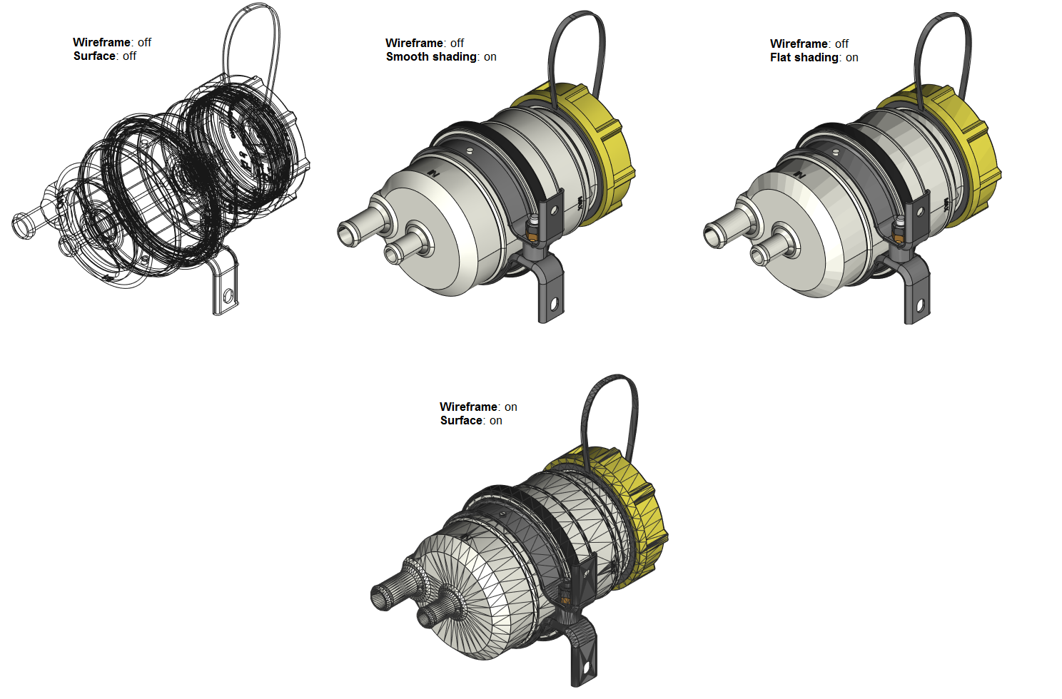
To customize the image visual style it is possible to use different combinations of options and display modes. The figure shows usage examples of different combinations of the Wireframe option and the Smooth shading, Flat shading, Hidden lines surface display modes.
Tools
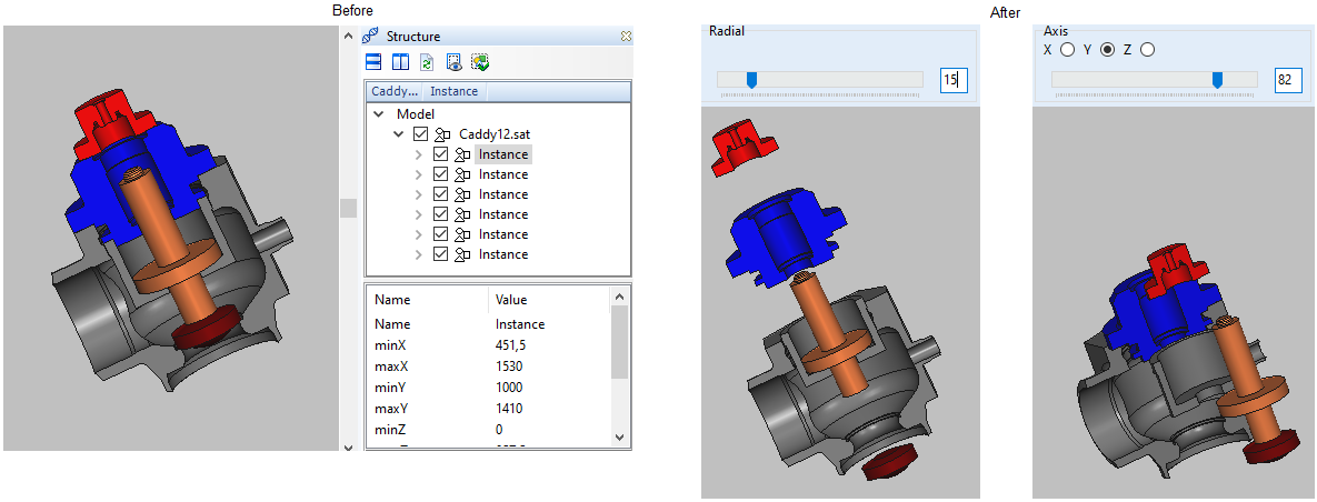
Exploded View. The tool allows exploding a 3D model to its components. There are two modes: Radial and Axis.
- Radial. Elements are exploded radially from the center of the model box at the specified distance.
- Axis. Elements are exploded along the specified axis away from the model center.
3D Section. The 3D Section panel includes controls to configure visual display of 3D models and cutting planes.
Navigation and Viewing
Selection mode. There is a setting allowing changing the selection mode of 3D model elements in the 3D Viewer mode.
- Select by Solid: The option enables you to select and highlight solids.
- Select by Face: The option enables you to select and highlight faces.
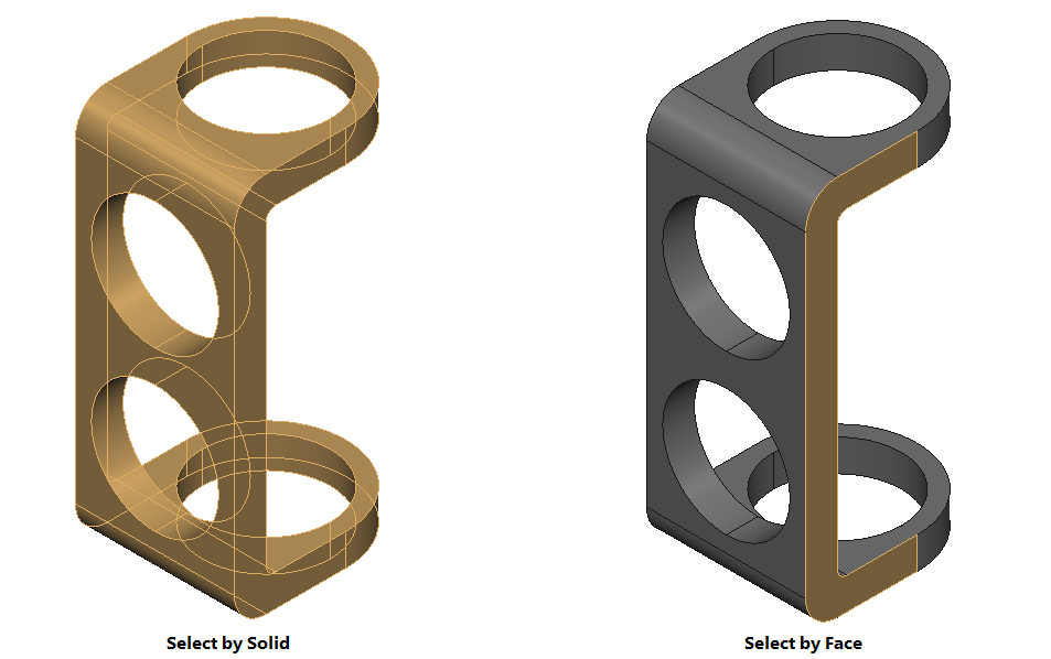
Note: Hold the Shift button to toggle between the Select by Solid and Select by Face commands while working with your 3D model.
Go to CADEditorX